
Many campsites now offer a boosted TV signal for motorhomes and caravans. You simply plug one end of the coaxial cable into the socket on the site’s hook-up bollard and the other into the back of the TV.
That’s all very well in warmer weather, but in winter, when we perhaps watch a bit more TV, it means leaving a window open so the lead can be fed through, or missing later shows so you can unplug the lead and close the window.
It also means that you might have coaxial cable trailing through the ’van before it reaches the TV. And many motorhomes, especially those with fixed beds, have more than one TV point and therefore might have more than one TV.
- Take a look at our best motorhome TV guide for help with finding the right model
Boosting the signal
One of our favourite campsites offers a boosted signal, but we’ve been lucky and managed to get a reasonable signal using the ’van’s antenna.
However, on occasions, my parents, on another pitch, have only been able to get reception using the boosted signal, despite having the same antenna set-up. At other sites, we haven’t bothered with the TV at all if the signal’s been poor. But when you can’t get a good TV signal, you can guarantee there’ll be something special you want to watch!
One solution is to have a satellite dish set-up, but even then, you’re not necessarily going to receive a good enough signal.
Many motorhomes have an external satellite TV cable socket, with a few also having a TV aerial socket. Ours has the external satellite TV connection and has satellite connections at each of the TV points. So is there any reason why this can’t be used for a TV signal? The simple answer is no. And it’s very easy to adapt the leads.
To do this, you’ll simply need:
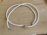
A length of good-quality coaxial cable to form the extension lead, plus a short length (50cm or so) for each of the TVs you have
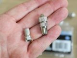
- Coaxial plugs
- ‘F’ plugs – screw-on type
- Stanley knife
- Wirecutters
It doesn’t matter whether you start with the long or the short cables, because they will end up having the same connections. At one end, you’ll need a coaxial plug (male), and at the other, an ‘F’ plug.
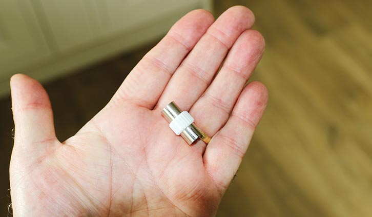
It’s also worth carrying a male-to-male coaxial adaptor in your spares, just in case the campsite bollard has a male connection.
Once you’ve made up your cables, test them by connecting the TV (satellite connection in the ’van to antenna socket in the TV), and the external cable. I plugged the external cable into a house socket at one end and the ‘F’ connector to the ’van’s satellite connection. It worked at all TV points.
Fitting an external TV antenna socket
But what if your motorhome has no satellite connection? Again, it’s quite simple to remedy.
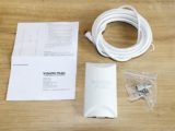
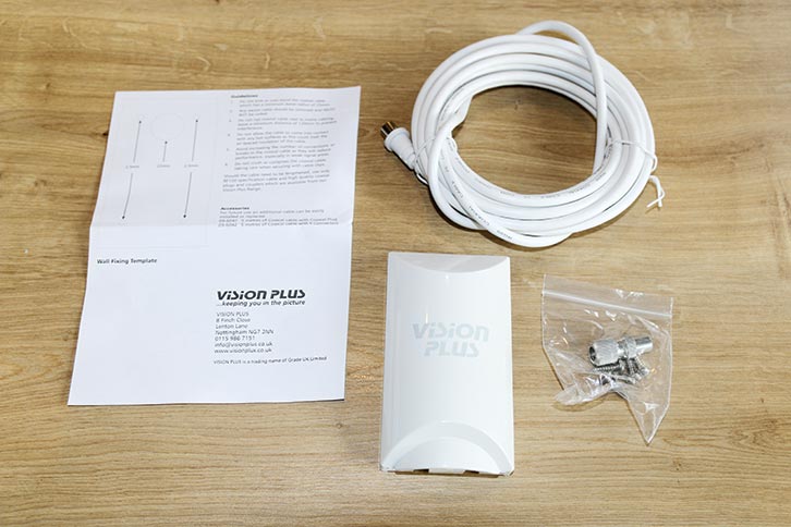
Vision Plus makes an external TV antenna socket which includes 5m of coaxial cable for this situation (other makes are available!).
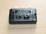
To avoid adding a second TV socket in the ’van or attempting to join coaxial cables (one from the ’van’s antenna and the other from the external socket), which might cause reception issues, I bought an isolation switch. This allows you to select which input to use – the ’van’s or the site’s.
For this job, you will need:
- Stanley knife
- Wirecutters
- Electric drill with 2.5mm bit and a 22mm hole cutter
- Large and small Pozidriv screwdrivers
- Cable ties/clips
- Double-sided numberplate tape
- 2 x coaxial ‘F’ connectors
First, you need to decide where to install the external socket. In our case, the motorhome’s antenna and the TV point were on the nearside, so we chose to fit the socket low down on the nearside, so the coaxial cable would feed into the ’van under the nearside seat/bunk. This also made the internal cable run relatively short.
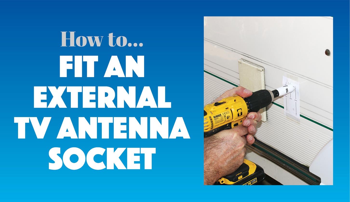
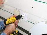
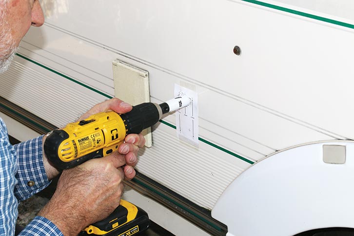
Vision Plus provides a template for the holes that need to be drilled. Having decided where the socket will go, cut out and attach the template to the ’van wall, and drill the holes. After removing the cable cover from the inside of the external socket, screw the back plate and sealing gasket into place, but only at the bottom and using the shorter of the supplied screws.
Next, feed the coaxial cable through the large hole and into the ’van, and clip the attached socket into place before attaching the cover, securing it with the smallest of the screws
in the centre and the larger screws in the top corners. It’s worth noting the hinged cover detaches to ease installation if necessary.
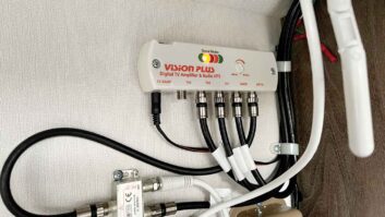
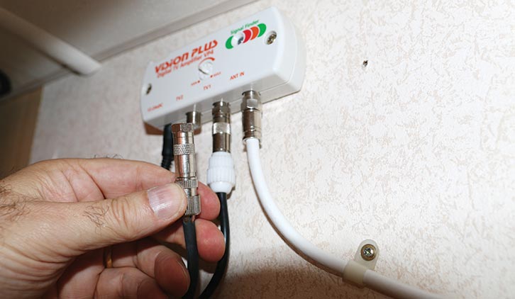
Working inside the ’van, decide where you are going to fit the isolation switch. In our case, it was under the TV amplifier in an overhead locker.
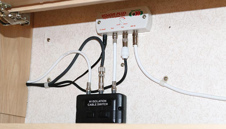
Detach the TV output connection from the amplifier and replace it with a section of coaxial cable (with an ‘F’ connector at both ends). It needs to fit between the amplifier and either of the outer connections (A or B) on the isolation switch.
Next, the cable to the TV point needs to be connected to the centre point on the isolation switch. Feed the cable from the external socket to the isolation switch (securing with cable ties if necessary), and after trimming its length, attach an ‘F’ connector and secure it to the remaining connection on the isolation switch (A or B).
Finally, secure the isolation switch unit to a suitable place. Rather than using the supplied screws, we used double-sided numberplate tape.
Again, we tested the installation by connecting the external socket to a house socket, and then switched the input to the motorhome’s antenna (switching on the amplifier if needed). And once again, it all worked a treat.
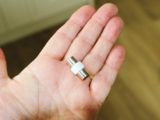
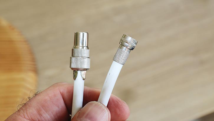
1. ‘F’ and coaxial connectors.
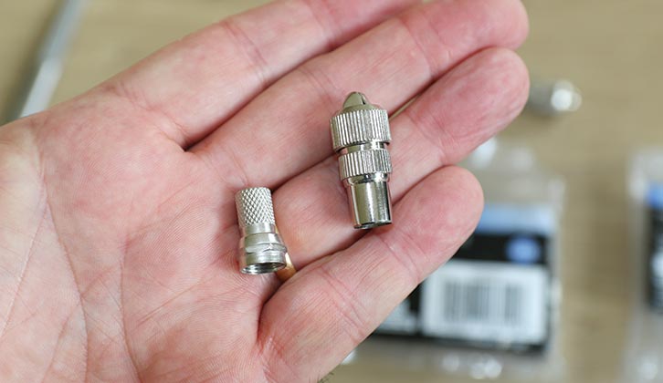
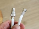
2. Attaching ‘F’ and coaxial connectors to coaxial cable.
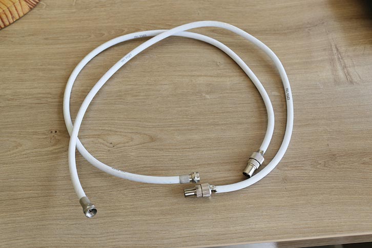
3. Short leads for the TVs completed.
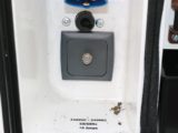
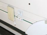
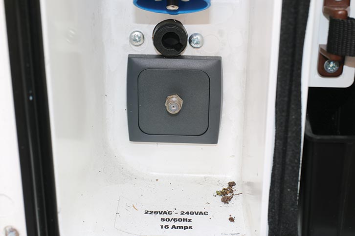
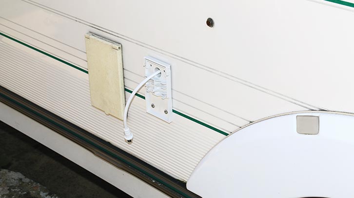
4. A motorhome’s satellite connection.
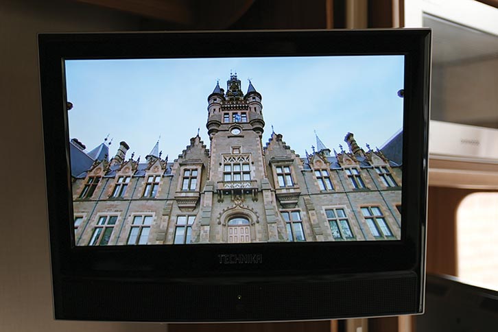
5. Perfect picture (in HD, too!).
6. Male-to-male coaxial plug adaptor.
7. The Vision Plus external socket kit.
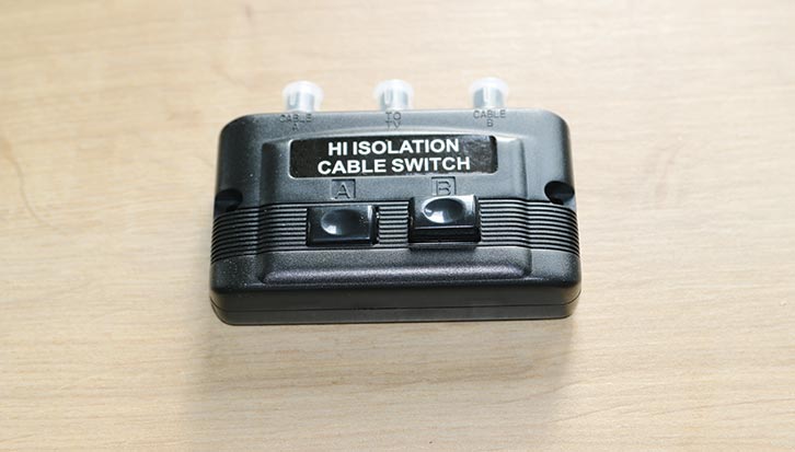
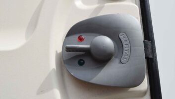
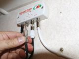
8. Isolation cable switch.
9. Template and drilling the holes.
10. Fitting the external socket.
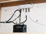
11. Fitting isolation switch and cables.
12. The finished job.
With thanks to Vision Plus for supplying the external socket
Future Publishing Limited, the publisher of Practical Motorhome, provides the information in this article in good faith and makes no representation as to its completeness or accuracy. Individuals carrying out the instructions do so at their own risk and must exercise their independent judgement in determining the appropriateness of the advice to their circumstances. Individuals should take appropriate safety precautions and be aware of the risk of electrocution when dealing with electrical products. To the fullest extent permitted by law, neither Future nor its employees or agents shall have any liability in connection with the use of this information. Double check any warranty is not affected before proceeding.
After more DIY projects? Then why not take a look at these:
- We explain how you can install QC 3.0 USB fast chargers and an 8-way fuse panel
- We talk you through how to look after your motorhome’s rubber seals
If you’ve enjoyed reading this article, why not get the latest news, reviews and features delivered direct to your door or inbox every month. Take advantage of our brilliant Practical Motorhome magazine SUBSCRIBERS’ OFFER and SIGN UP TO OUR NEWSLETTER for regular weekly updates on all things motorhome related.