


Almost all new motorhomes for sale come with a form of ambient lighting, and in some cases it’s dimmable, too.
I was recently looking around my parents’ aging ’van with my son, James, and realised that there isn’t a single LED light in it. All the illumination is either via mains bulbs, or power-hungry 12V halogen units.
We wound things back from James’s suggestion of disco-style lights, but decided that an upgrade to LEDs wouldn’t be a bad idea.
In the first instance, though, we decided not to simply replace the 12V bulbs with LED types, but to add another dimension to the lighting system that’s quite easy and cost-effective.
What do you need?
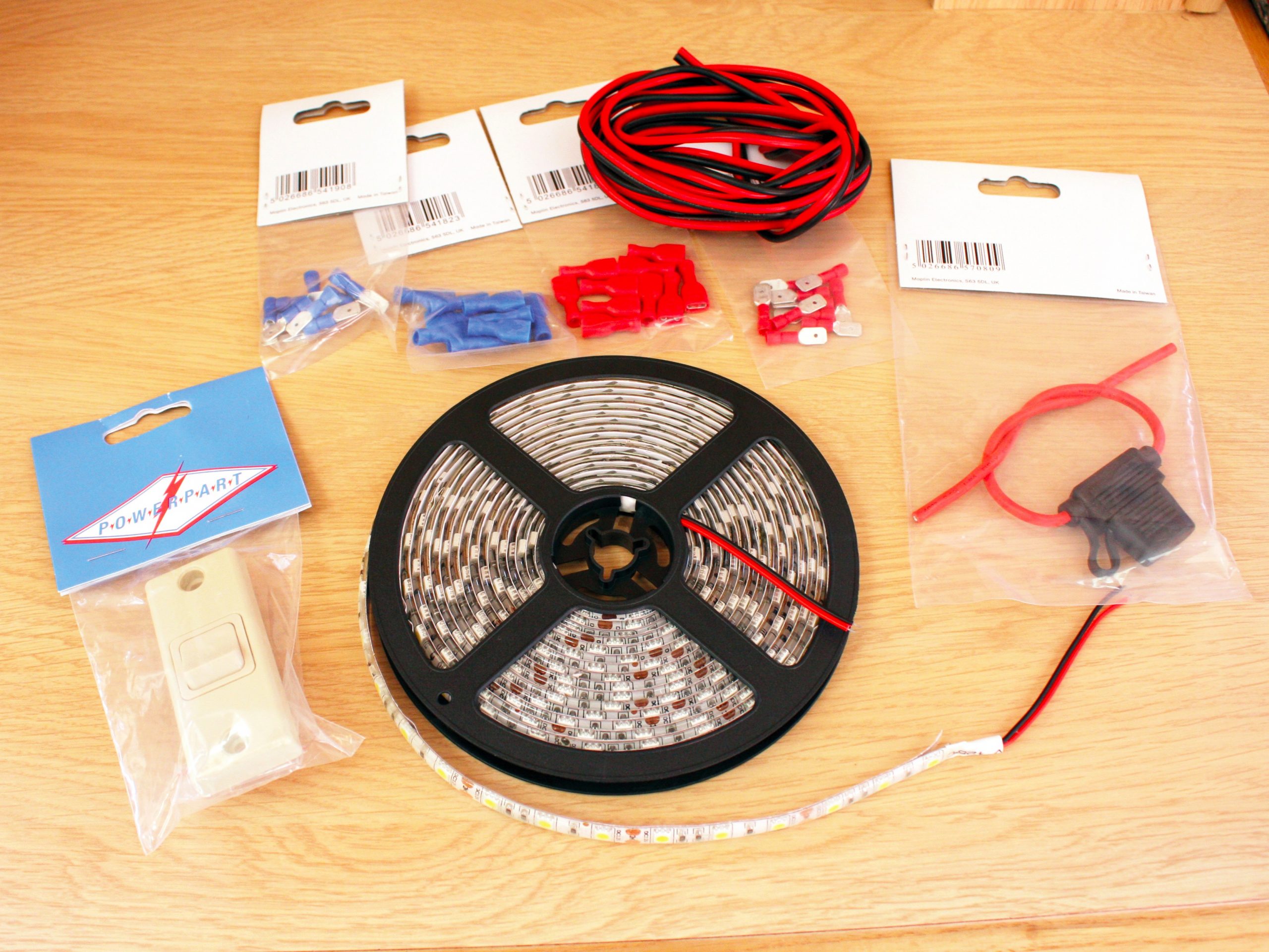
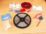
First, I gathered a couple of 5m reels of self-adhesive LED ribbons, some 1mm square (core) cable, a switch, a waterproof blade-fuse holder, male and female insulated crimp connectors, cable-ties and heat-shrink wrap. The total cost was about £30.
Because James has a degree in electrical engineering, I thought it only right to enlist his help.
Tools required are:
- 22mm flat wood bit and drill
- Craft knife
- Small crosshead and flathead screwdrivers
- Wire trimmers and cutters
- Crimping tool
- Soldering iron
- Scissors
- Staple gun
Where’s it going?
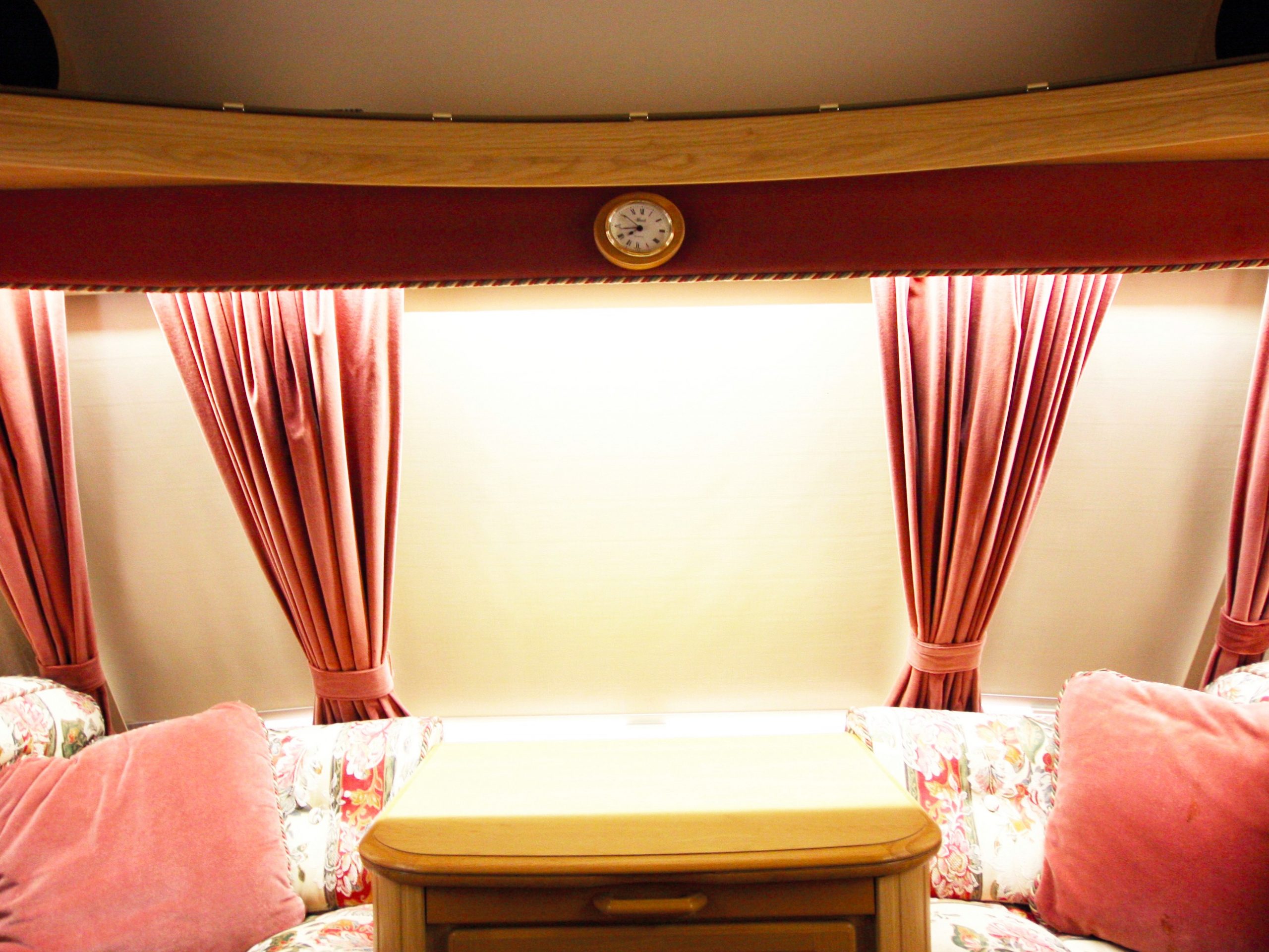
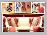
We then planned where everything would fit, including the switch, cabling and LED ribbons.
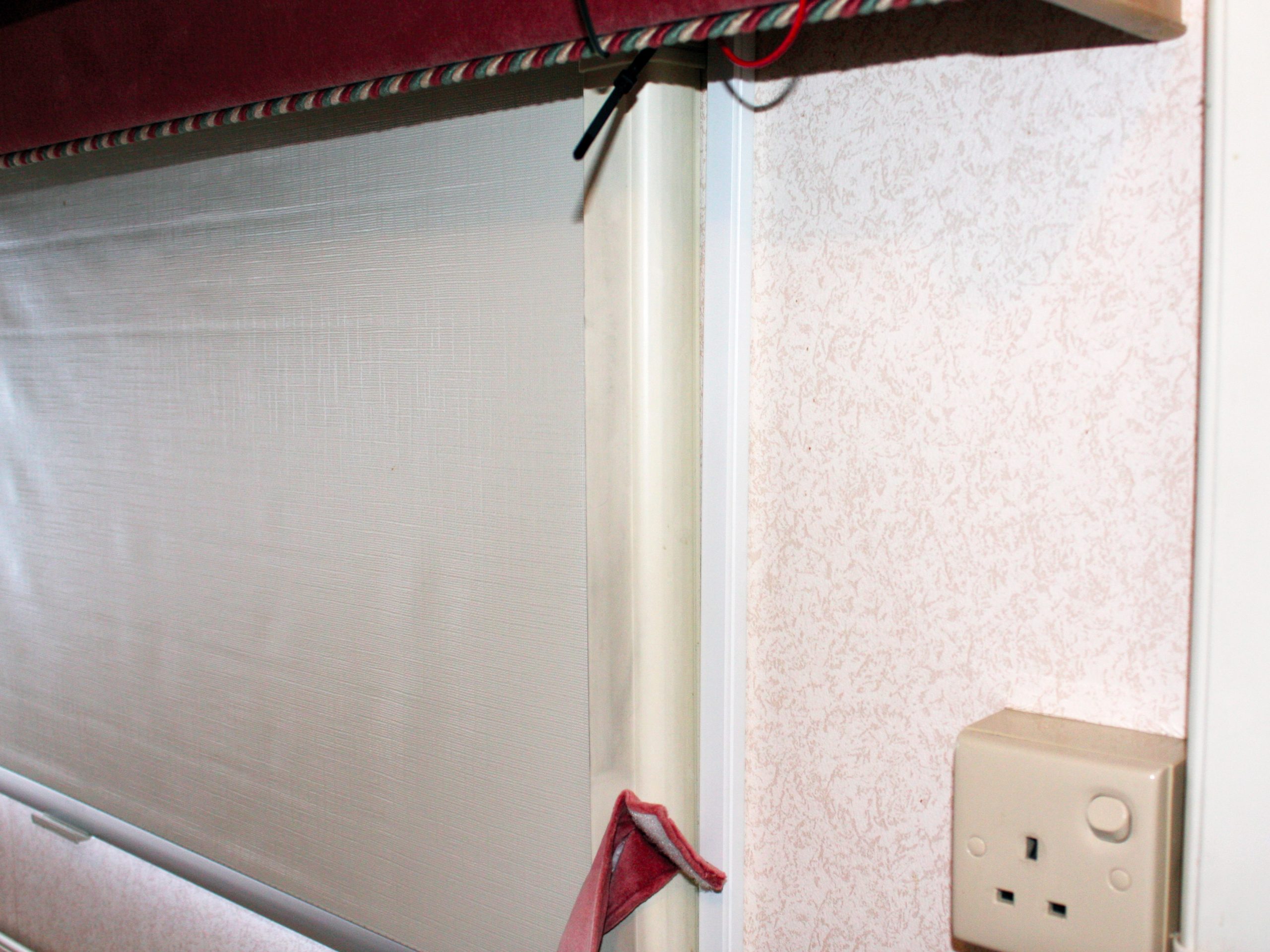
We also removed the curtains from around the rear lounge to gain better access – these pop out of their tracks.
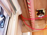
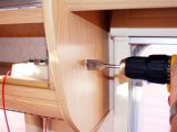
Once that was done, we started with the switch. Using the 22mm flat wood bit, a hole was cut through the wooden panel at the end of an overhead locker that offered access from behind.
The switch would operate on the power/live (positive) side of the electrics, so we cut two lengths of red cable: one that was long enough to connect to the battery (with some to spare), and another that would go from the switch to the LED ribbon beneath the overhead locker.
You’ll also need a length of black cable for the return side (negative), which will run from the LED ribbon to the battery.
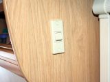
To keep the job tidy, crimps were put onto the ends of the cabling before we connected them to the switch. The latter was then fastened to the outside of the overhead locker.
Keep it neat and tidy
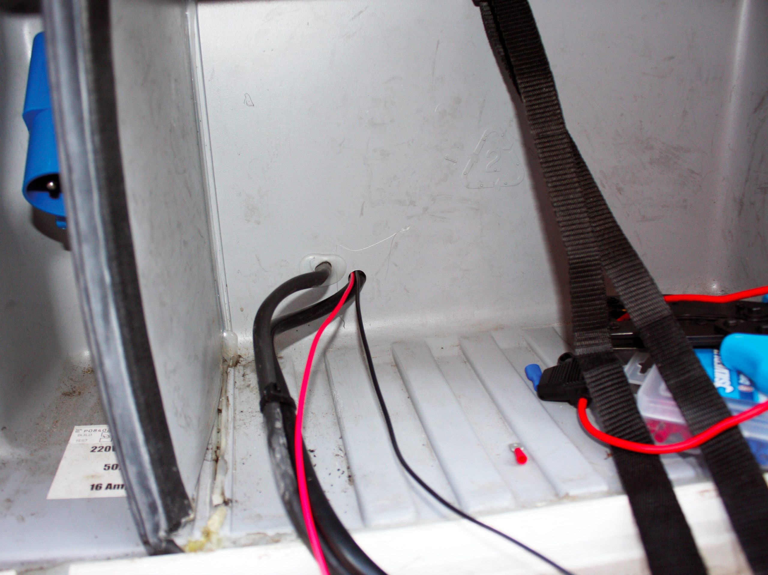
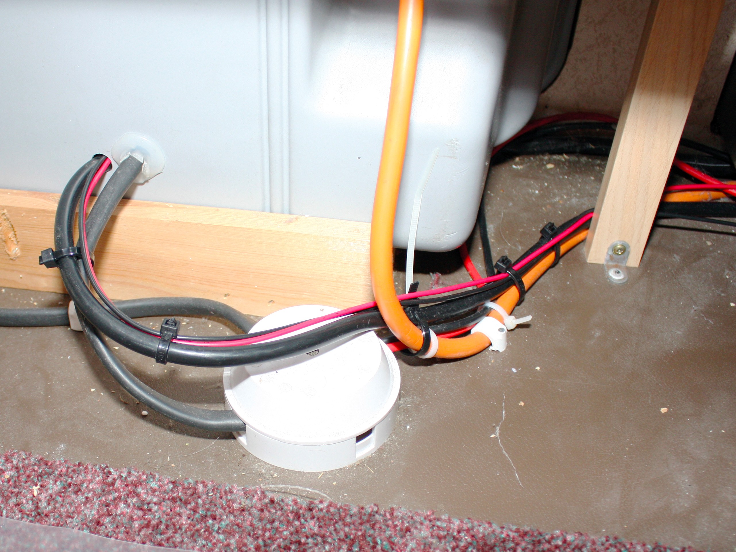
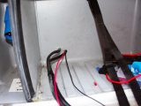
Our motorhome’s leisure battery is located in an external locker. After recently fitting a solar panel to the ’van, we were able to use available holes and trunking to route both the positive and negative cables from within the locker down to the battery.
If you don’t have this option, or if your ’van has an internal leisure battery, self-adhesive trunking can be bought.
The pre-wired fuse holder was connected to the end of the red positive cable as close to the battery as possible, using insulated ‘male’ and ‘female’ crimp connectors. Cable-ties were employed to keep the cabling tidy.
After running the new cabling alongside the original battery connections, we again kept things neat with ties and insulating tape. A 10-amp blade fuse was then fitted into the holder.
Moving back inside, insulated female crimped connectors were secured to the negative (black) cable and the positive (red) cable from the switch.
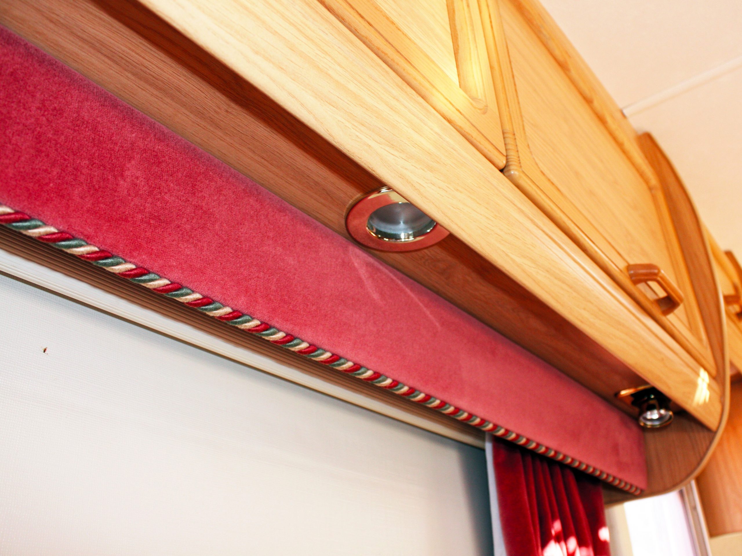
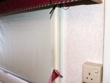
Our LED ribbons were going to run behind the rear-lounge pelmets, so we needed three strips: one for each side, and another to go across the back.
After measuring each length, the LED ribbons were cut. Look at them closely and you’ll see that they’re marked where you can cut them (across a copper contact). Make sure that you only snip across this contact, or some of the LEDs won’t work.
You’ll also see that each side of the contact is marked + or -.
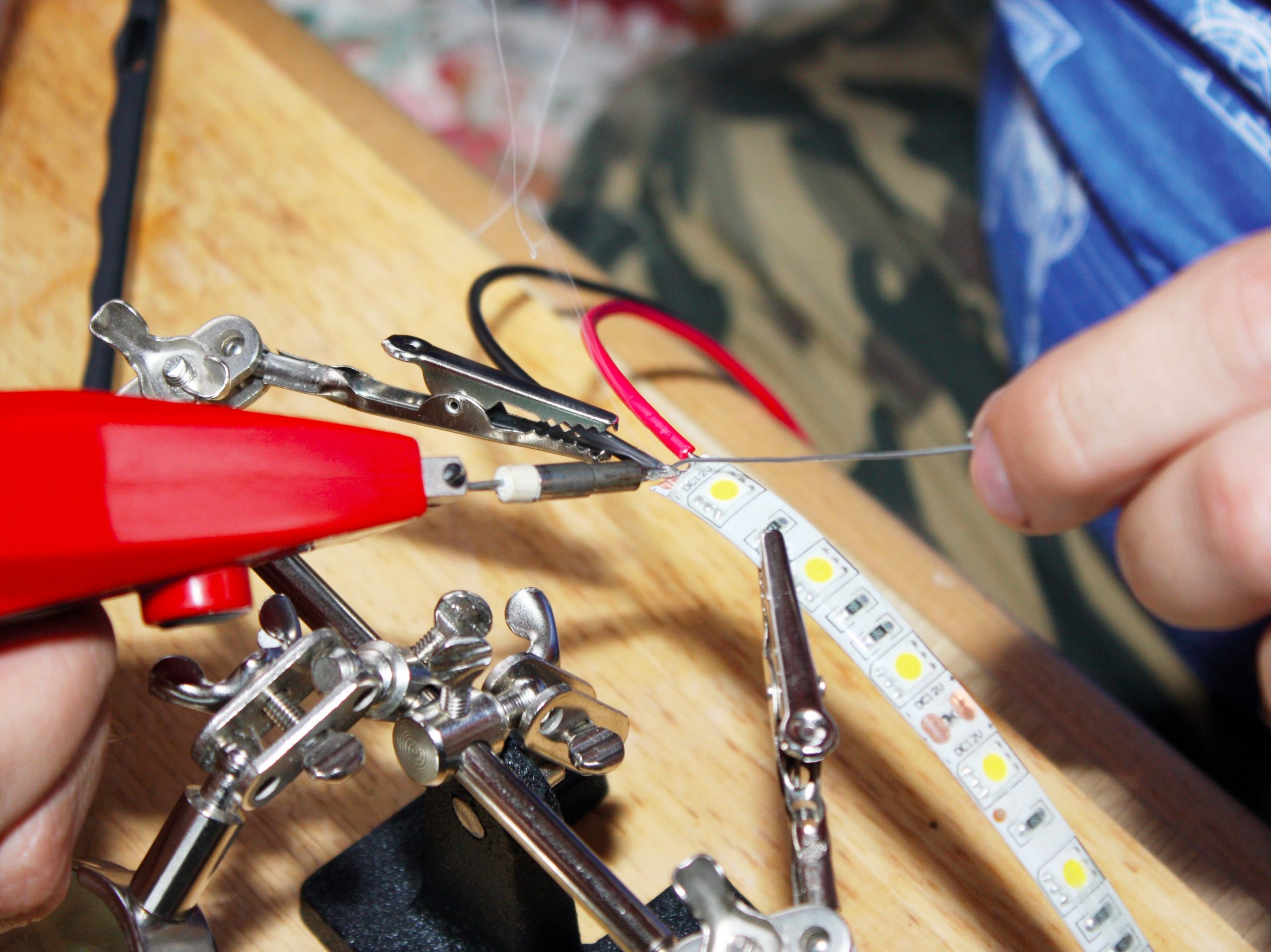
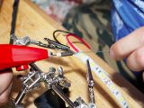
Soldering on
Then, remove the plastic-type covering from the copper contacts using a Stanley knife. Be careful not to cut the contacts off by going too deep. You don’t need to remove the covering from the final end.
In order to negotiate the corners in the ’van, short lengths of cable were soldered between the two positive and negative copper contacts on each strip of LED ribbon.
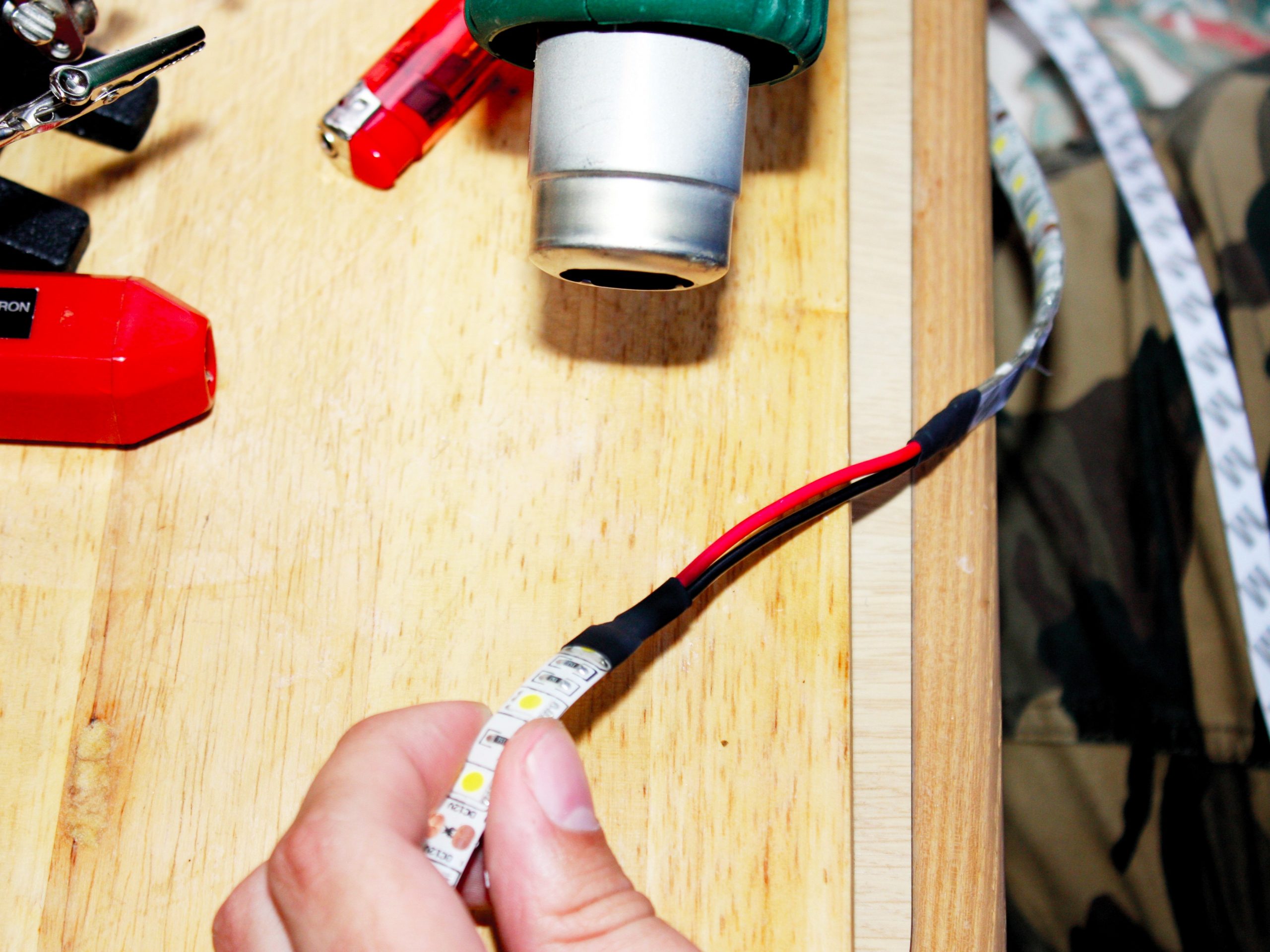
When one end of both cables had been soldered, heat-shrink was used to insulate the contacts. Remember to put on a second piece of heat-shrink before soldering the other ends of the cable.
You’ll also need to solder a couple of short lengths of both cables to feed the power from the switch and on the return side. Fit the other ends of these cables with male crimp connectors.
The big switch-on
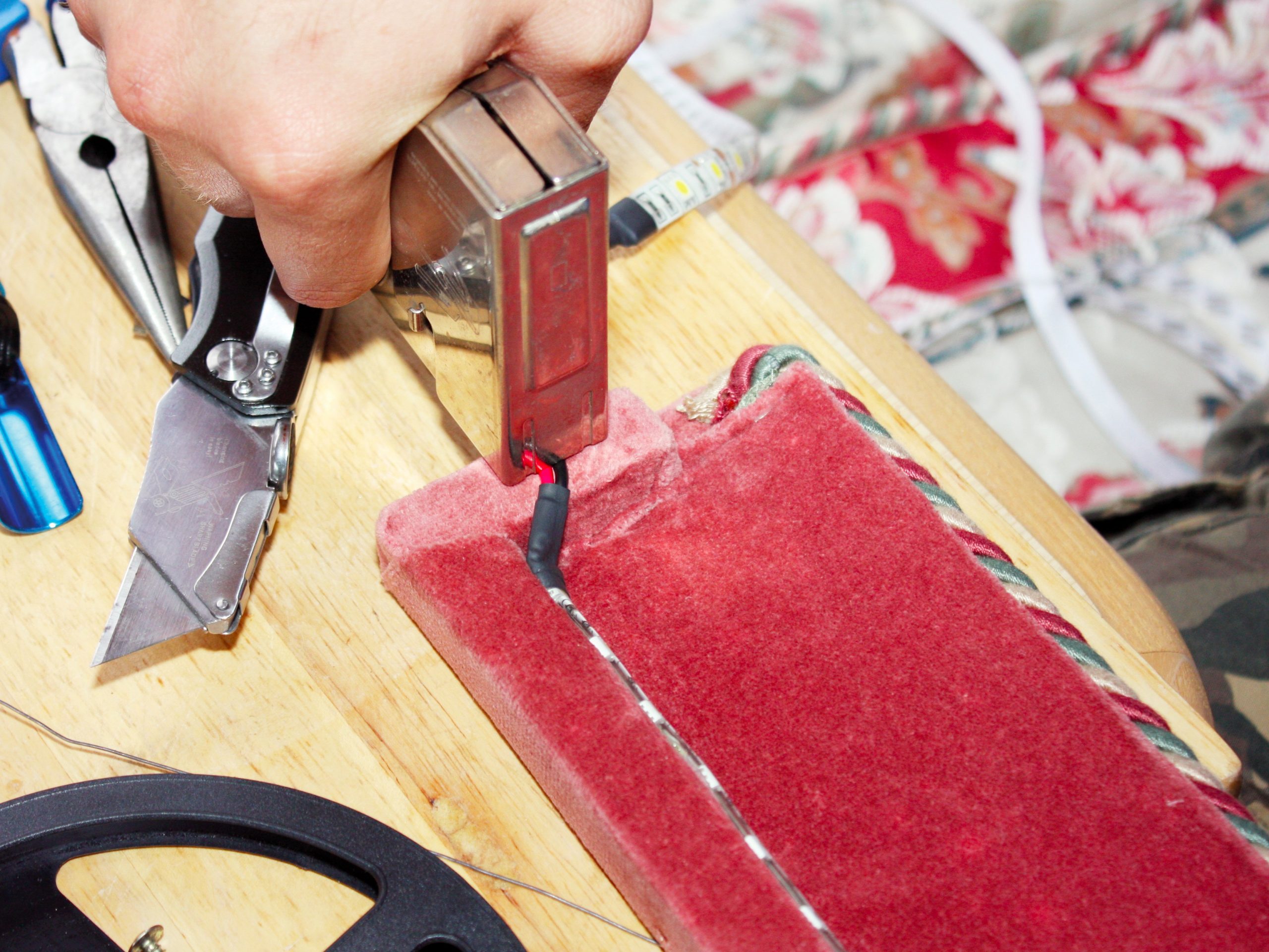
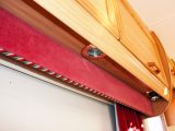
It was then time to attach the LED ribbons to the pelmets. Initially we removed one of the pelmets to fit the strip, but found there was enough access without.
However, while it was off, we used a staple gun to secure the cable that would lead to the switch to the back of the pelmet, to give added support (ensuring that we didn’t nick the cable).
After checking that the first LED ribbon (nearest the switch) was in the correct place, short sections of the backing on the self-adhesive strip were removed at a time, and the ribbon pressed firmly into place.
With all of them secured, the short sections of cable were held secure (and out of the way) using self-adhesive cable ties.
It was then time to reconnect the battery and test our handiwork.
IMPORTANT! Disconnect any mains supply and the 12V battery before you start.
We decided that an upgrade to LEDs wouldn’t be a bad idea – the total cost was about £30