


It’s amazing how much motorhome lighting has improved – in the main, thanks to LEDs. Not long ago, ‘vans were lit by power-hungry halogen bulbs and fluorescent strip lights. Not only were halogens power-hungry – they also became very hot, which could make sitting below one uncomfortable.
Improved lighting
Over the years, we’ve upgraded the lighting in our son James’s 1999 Abbey caravan, swapping halogen bulbs for LEDs and installing new LED ambient lighting in the lounge.
It’s a fairly simple procedure, and we were impressed with the results. So we knew what to do when the unhelpful lighting in our ‘van kitchen started to irritate! We decided to change the old fluorescent strip light and install LEDs.
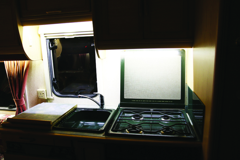
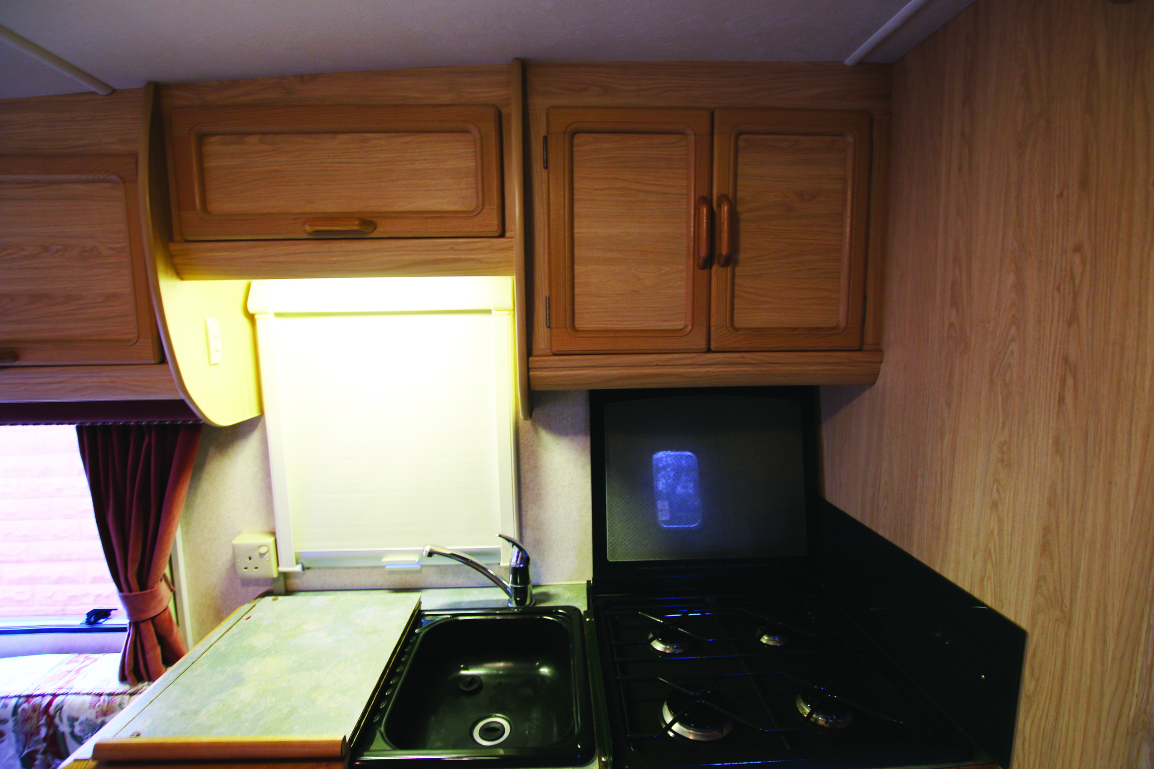
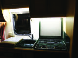
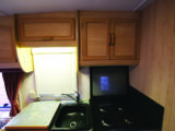
Part of the problem in our kitchen was that the overhead locker bases are at different heights. The sink was lit, but the cooker wasn’t, compounded by the fact that if you stood in front of the cooker, you blocked out the illumination from a nearby ceiling light. So it really was time to upgrade.
We already had some self-adhesive 12V LED ribbon lighting, left over from previous jobs, that would be perfect for this, because we could not only replace the fluorescent light, but also add extra lighting to the cooker area.
Parts and tools for this job are:
- Self-adhesive LED ribbon lights
- Switch
- 1.0mm and 0.5mm core cable (red +ve and black -ve)
- Crimped spade terminals (male and female)
- Crimped pin terminals
- Double-sided foam tape
- Cable ties
- Heat-shrink
- Stanley knife
- Assortment of screwdrivers
- Scissors
- Soldering iron and solder
- Electric drill and wood bits
- Wire trimmers and cutters
- Crimping tool
- Heat gun
Before beginning the job, make sure that both the 230V mains supply and 12V batteries are disconnected.
The electrical power to the original light fitting is more than sufficient for LED lighting ribbons, so the wiring for this is pretty straightforward.
- If you’re new to soldering, be sure to take a look at our how to solder guide.
Cut the ribbons
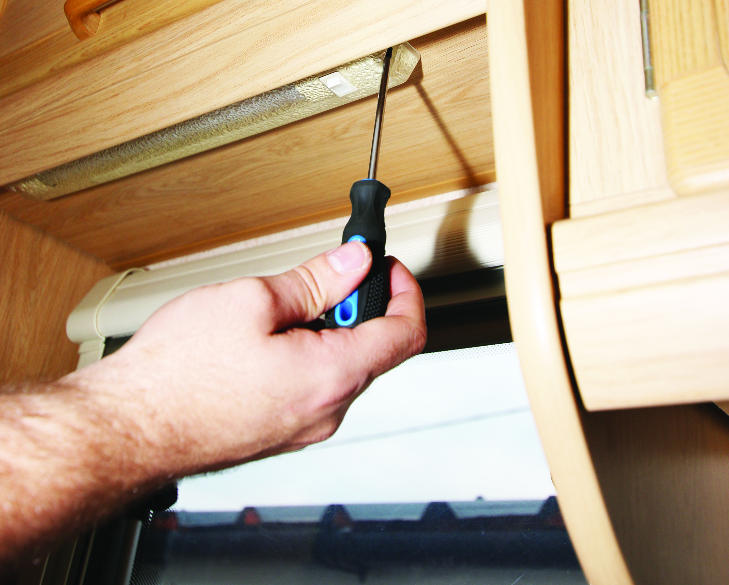
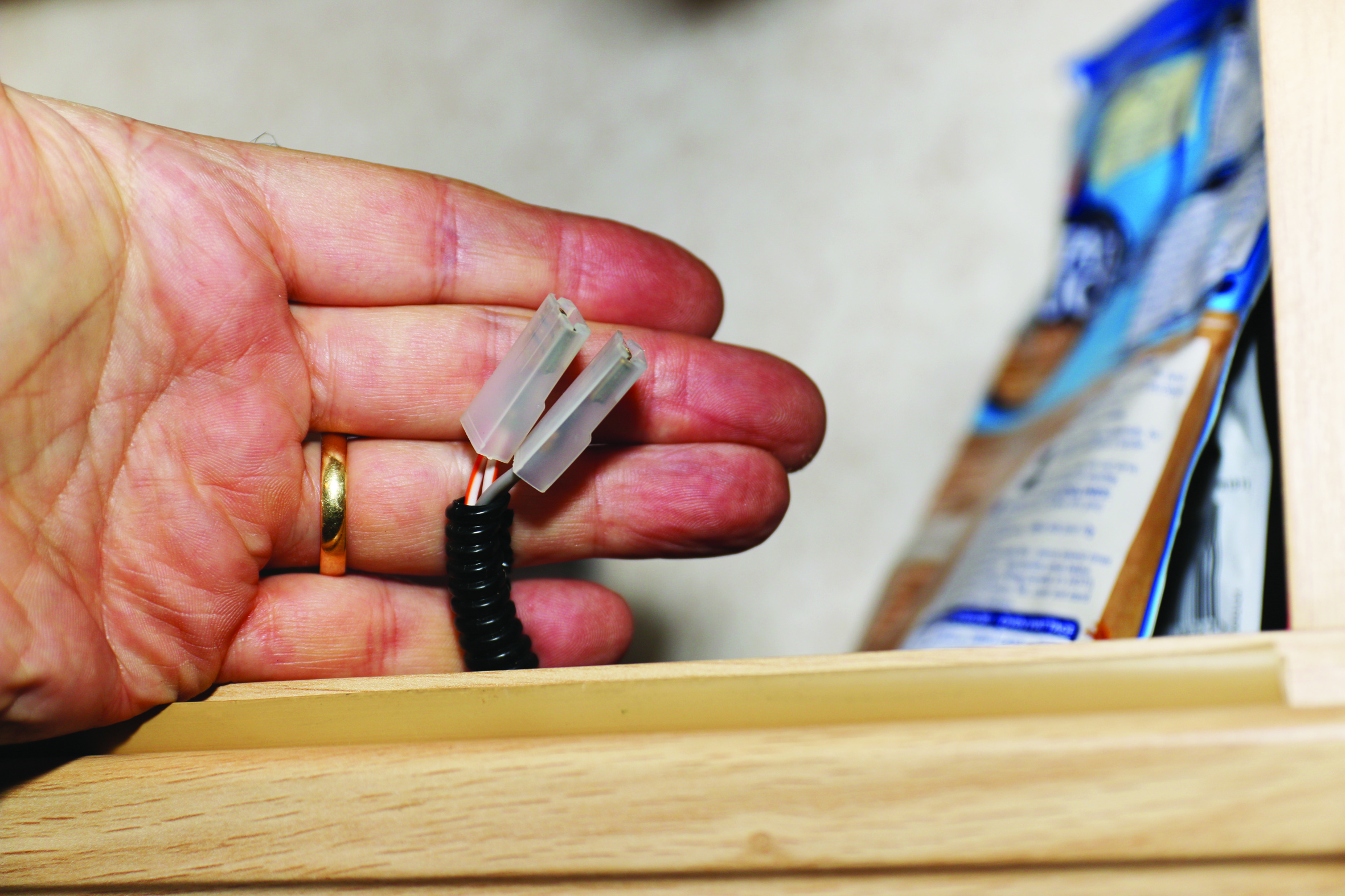
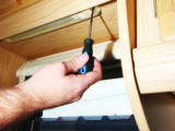
The first stage is to remove the original fluorescent light fitting. Ours was held with a screw at each end. When these were removed, the fitting was pulled down and the electrical connections unplugged. The fitting was discarded.
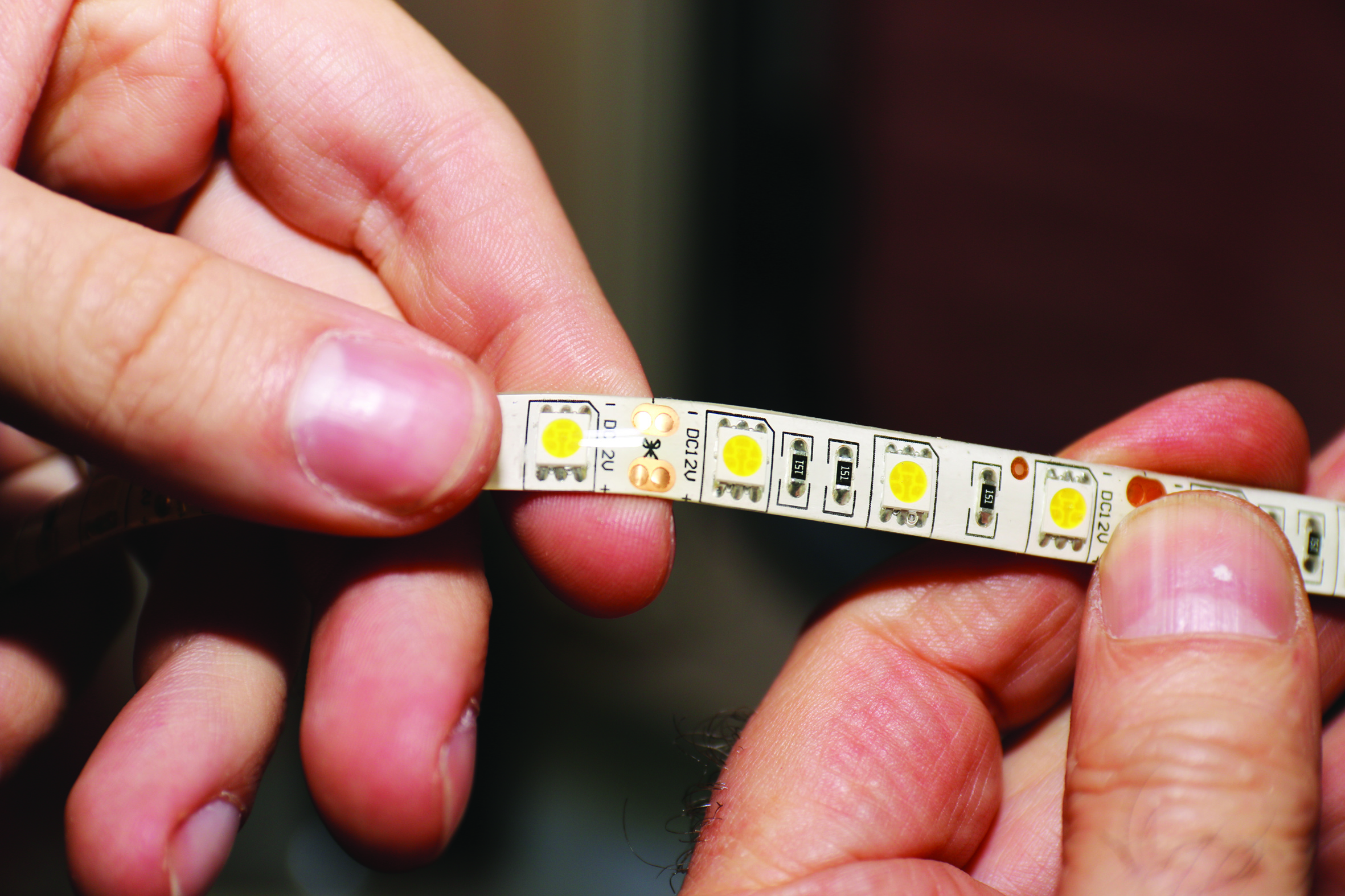
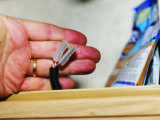
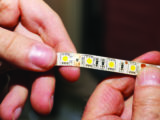
Next, starting with the LED ribbons, we measured and cut required lengths for each strip. If you look closely, you will see some small copper areas on the ribbons with a scissor icon in between – this is where the ribbon must be cut. Then we needed to extend the wires on one strip – which already had black (-ve) and red (+ve) wires attached because it was at the end of the ribbon – and add them to the second.
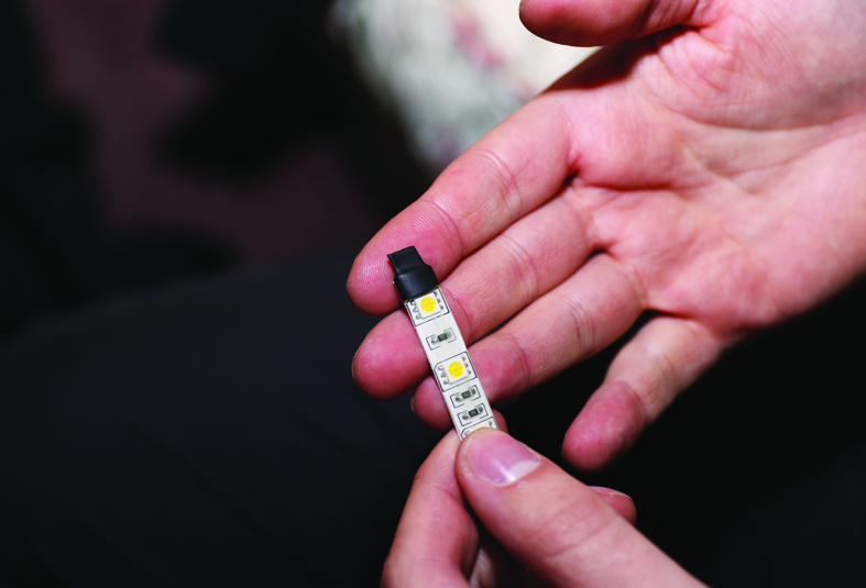
Before doing that, heat-shrink was put over the other ends of each strip, to keep any moisture at bay.
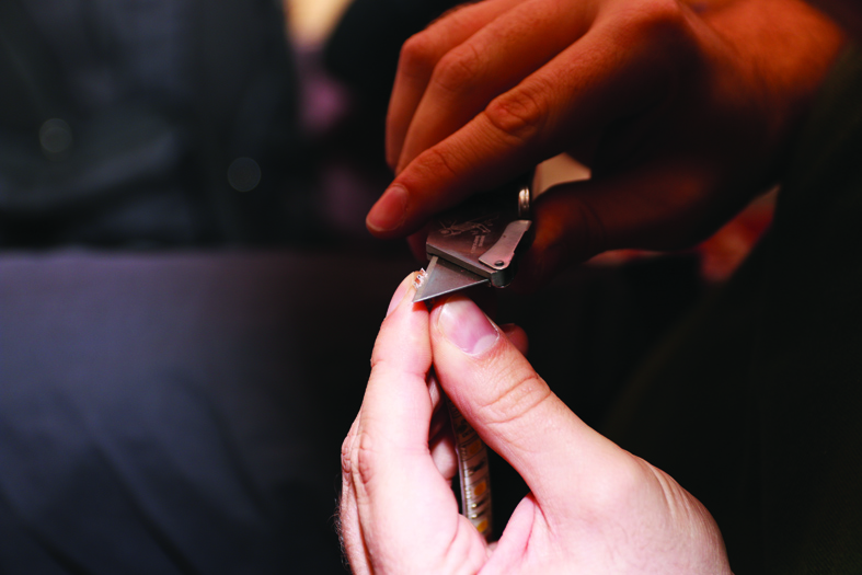
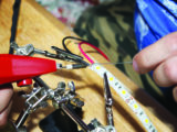
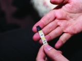
On the copper areas at the end of the ribbon, you’ll see a ‘+’ and ‘-‘ sign. A red wire needs to be attached to the ‘+’ and a black wire to the ‘-‘. To do so, the ribbon’s silicone covering must be trimmed, to expose the copper.
Solder enough of each wire (the red needs to reach the switch, the black to connect to the earth lead on the ‘van’s original wiring) to allow them to reach their respective connections.
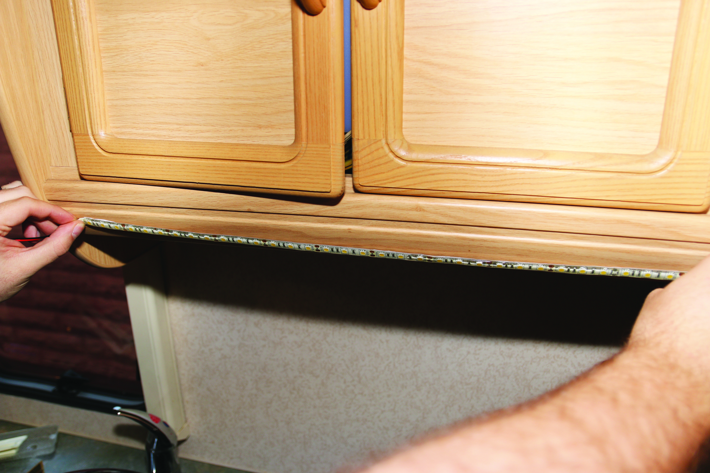
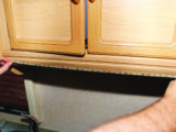
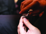
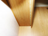
Then, using the self adhesive strip on the LED ribbon and double-sided foam tape (trimmed to the same width as the strips), the strips were attached under the lockers.
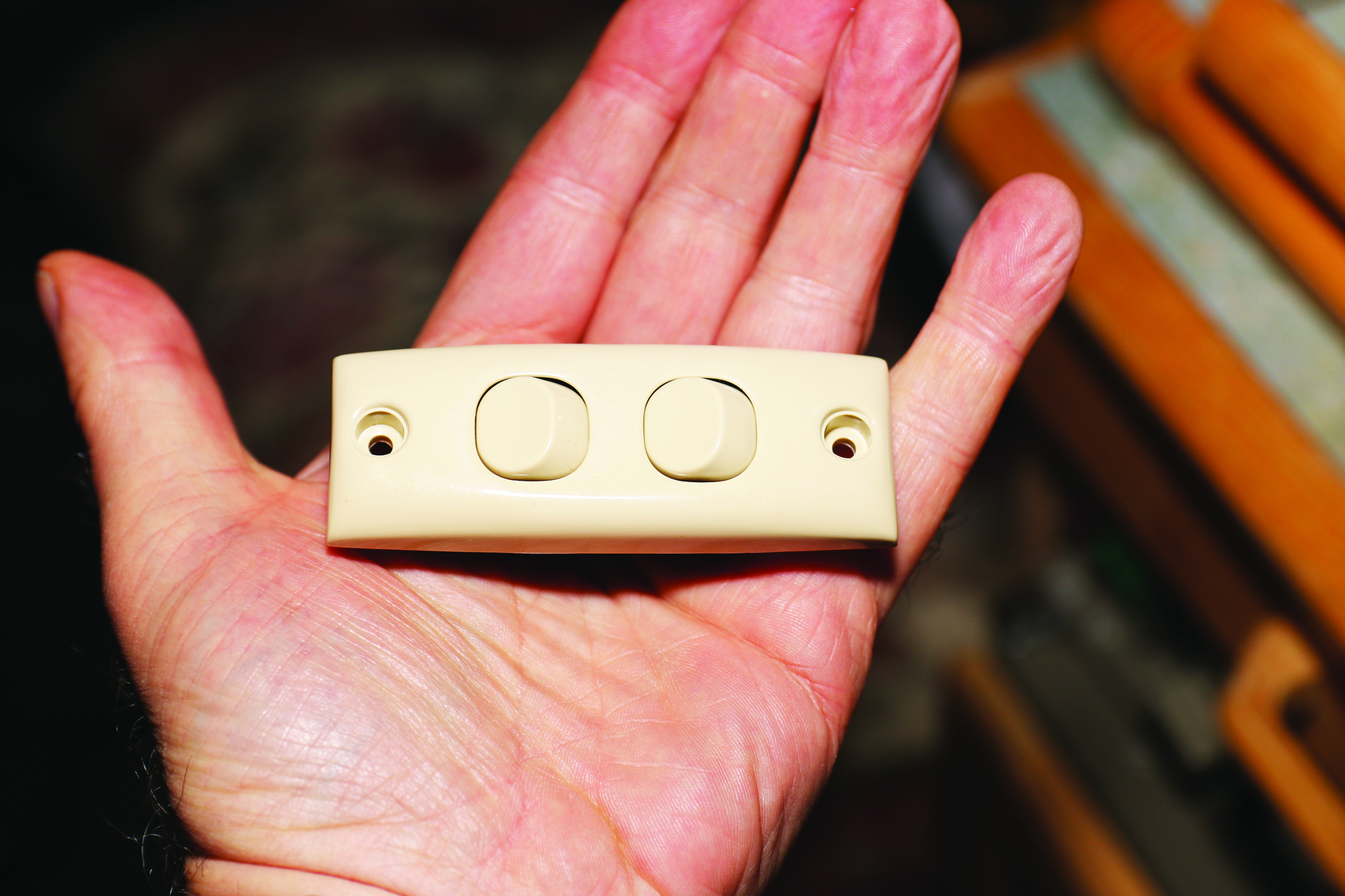
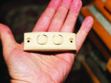
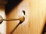
Next, we found a suitable place for the switch, marked this on the panel and drilled a pilot hole in the centre. This was opened out to the desired size with a 22mm bit.
Ours was a double switch (the only one that matched other switches in the ‘van), so two holes were needed. A slot was cut between the two for wiring.
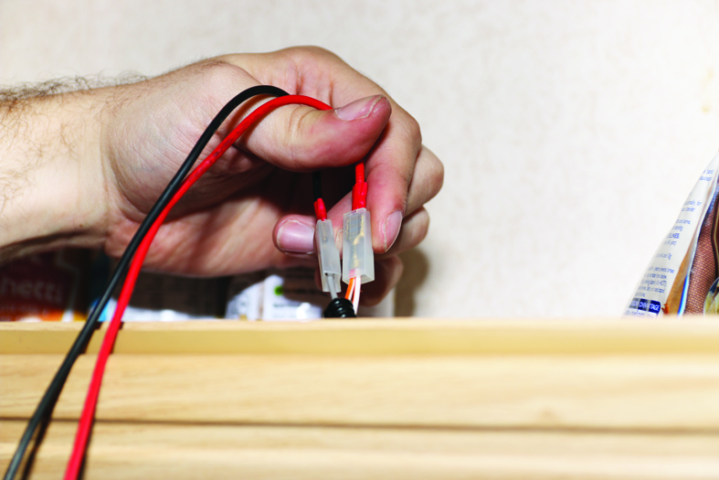
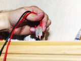
Starting with the power feed (red +ve), a male crimped spade terminal was attached to one end of the wire (this would attach to the original motorhome wiring), and at the switch end, this and a piggy-back wire were crimped into pin terminals.
The pin terminals were secured into the centre connections in the switch’s two terminal blocks.
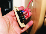
The red +ve wires from each of the LED lighting strips were secured into the top terminals on the switches.
Both black (+ve) wires from the LED strips were joined in a female crimped spade terminal, which in turn was attached to the motorhome’s original wiring spade terminal.
Before securing the switch in place, the leisure battery was reconnected, so we could test everything.
Then the switch was secured and the wiring tidied up with cable ties, so that it wouldn’t get caught inside the cupboard over the cooker area.
We had been planning to use a single switch for both strips, but the age of the ‘van meant the only one in the accessory shop that matched the originals was a double.
We could have wired both strips into one switch, but wiring them separately gives flexibility, and at least makes use of both of the switches!
Have a look at the images for a step-by-step guide.
If you liked this… READ THESE:
If you’ve enjoyed reading this article, why not get the latest news, reviews and features delivered direct to your door or inbox every month. Take advantage of our brilliant Practical Motorhome magazine SUBSCRIBERS’ OFFER and SIGN UP TO OUR NEWSLETTER for regular weekly updates on all things motorhome related.
Future Publishing Limited, the publisher of practicalmotorhome.com, provides the information in this article in good faith and makes no representation as to its completeness or accuracy. Individuals carrying out the instructions do so at their own risk and must exercise their independent judgement in determining the appropriateness of the advice to their circumstances. Individuals should take appropriate safety precautions and be aware of the risk of electrocution when dealing with electrical products. To the fullest extent permitted by law, neither Future nor its employees or agents shall have any liability in connection with the use of this information. You should check that any van warranty will not be affected before proceeding with DIY projects.
Part of the problem in our 'van kitchen was that the sink was lit, but the cooker wasn't, so it really was time to upgrade