Reversing a large motorhome is tough, as is coping with blind spots when in transit. That’s why I fitted a 360˚ camera system and saved money by doing it myself. You can catch up with part one of this DIY 360° camera project to find out more about the The Universal Parking Assist System that I chose, and why I selected it to install in my motorhome.
A standard tool kit sufficed for the project. Before starting work, I connected and powered up the system to ensure it functioned properly.
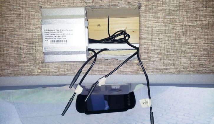
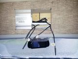
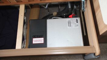
I cut a rectangular hole in the fascia above the cab and fitted the system’s processor box, which combines the views of the four cameras into a simulated overhead view that is transmitted to the display screen.
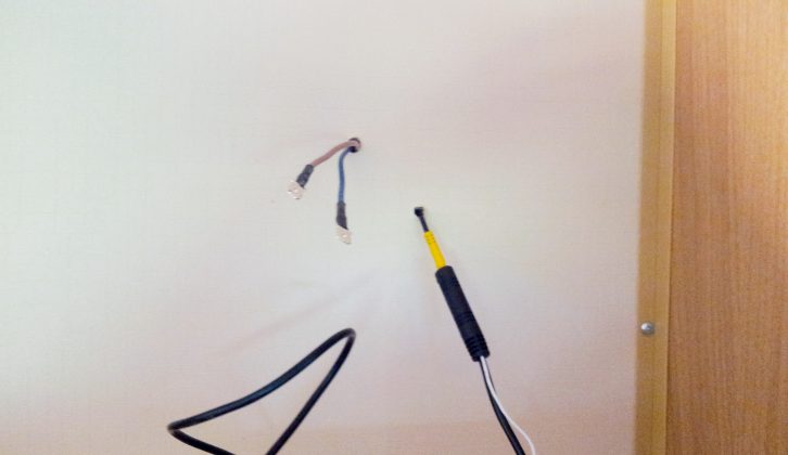
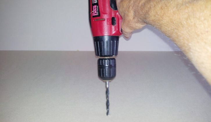
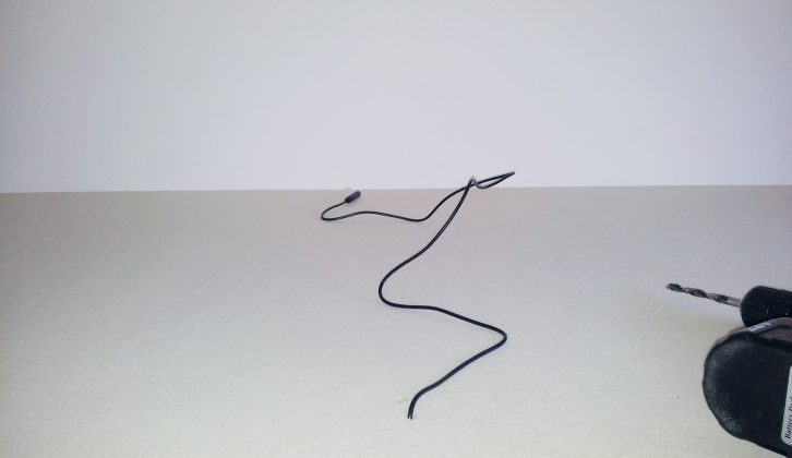
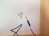
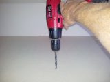
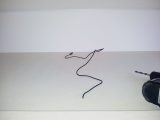
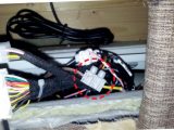
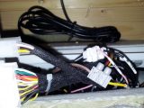
I fed the cables from the rear and two side cameras behind fascia, through lockers and wherever I could conceal them. I connected the cables, all labelled, to the wiring loom. Note that, whenever you drill into the motorhome’s sidewall, extra care must be taken, and all openings properly sealed.
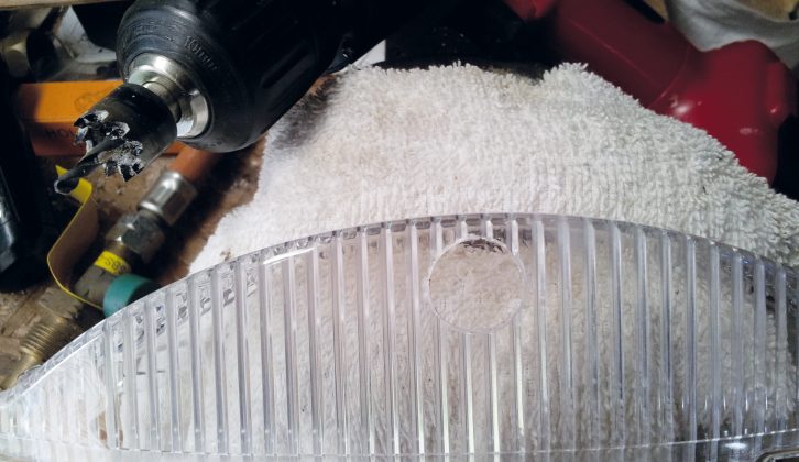
Left and right camera housings
The system I bought is primarily intended for cars, so the left and right cameras are designed to be push-fitted onto the underside of the car door mirrors.
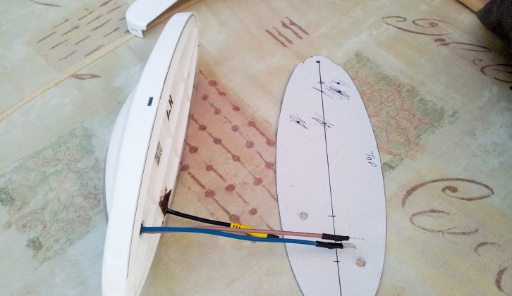
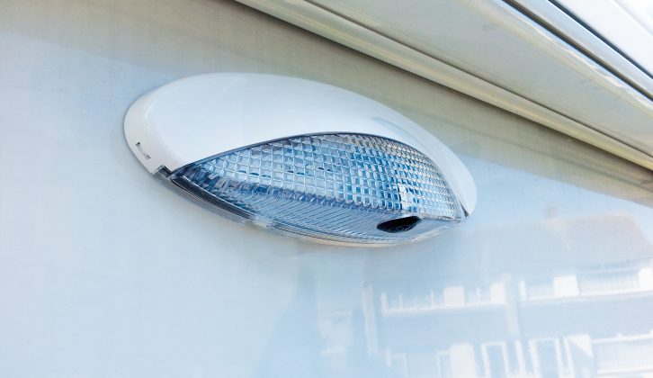
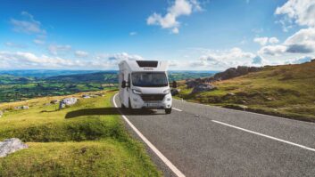
I chose not to do this and opted instead to place my cameras approximately halfway along the length of my Elddis Autoquest 130 motorhome and as high as possible.
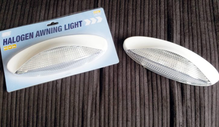
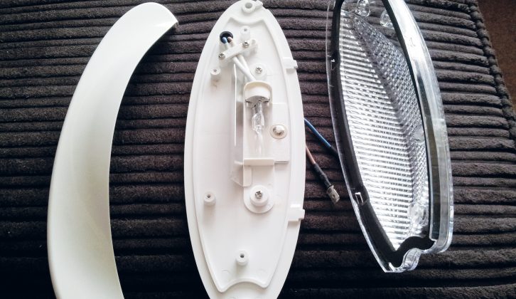
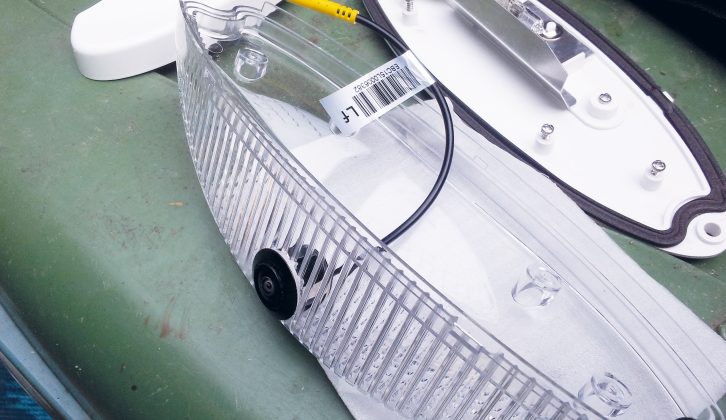
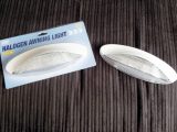
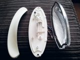
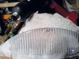
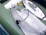
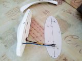
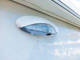
Various homemade options were tried but didn’t prove particularly successful. I despaired of making a suitable housing myself and then came the eureka moment: I happened across the Maypole awning light – perfect! This unit looks good, has the right shape (ideal for deflecting branches on the near side) and has sufficient room for the camera.
It is perhaps worth mentioning at this stage that all four cameras – on both sides, and at the front and rear – should be angled so that each sees some of your motorhome. This, along with other information, will allow the system to calculate the footprint of the motorhome during the setting-up phase.
With the external work done and the cameras plugged in, any excess cable can be coiled up inside a suitable cover (I used the two halves of a spare project box). The cable can then be clipped or, in this case, glued into place.
Placement and fixing for the right-hand camera is identical to the left but be careful that the light and camera wires emerge into the middle cupboard and not either side of the divider.
As far as the lights in the two Maypole units are concerned, I have currently not connected them up. If I eventually do, I’ll replace the halogen lamps with the cable and housing for the front camera.
Front camera cable and housing
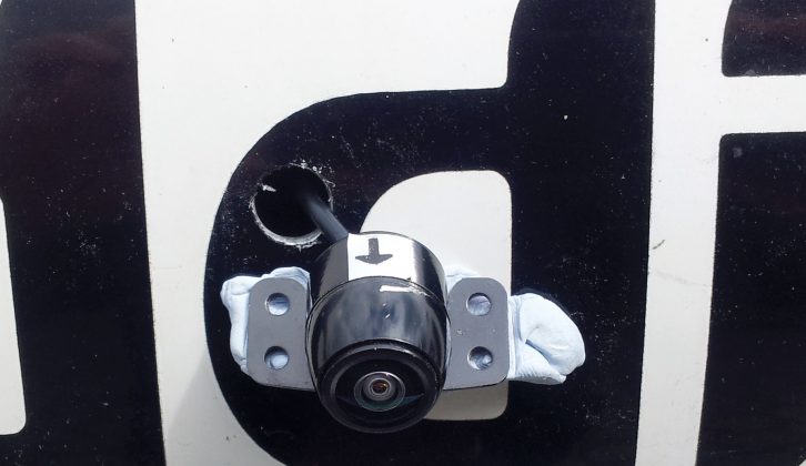
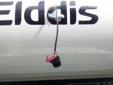
This last construction section was by far the most daunting, because I had decided to place the front camera on the leading edge of the Autoquest’s ‘bulge’, where the overcab bed is located. This would give the best downward view and would put the front camera at roughly the same height as the others.
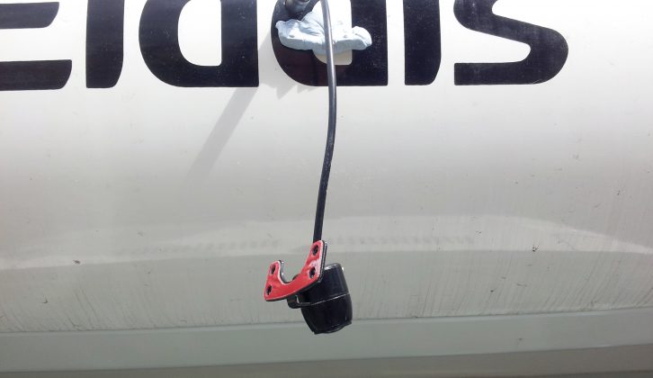
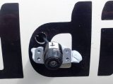
This positioning also allowed me to disguise the camera partially within the second ‘d’ of the ‘Elddis’ logo. This did dictate that it wouldn’t be exactly in the centre, but it’s close enough.
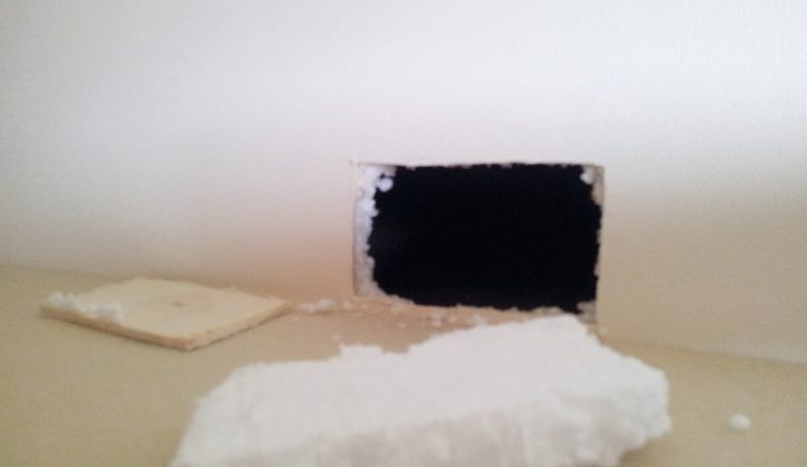
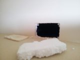
As for replacing the cut-out, I cut a small notch at the bottom of the ply where the cable comes through, then pushed the foam and ply back into the hole (you could use sealant if you desire) and taped over the gaps. If I need access to this area in future, it will be a simple matter to remove the panel. The mattress is thicker than the original, so it hides the panel.
Once the camera was screwed into place and sealed, I considered fitting some form of cover. After a lot of hunting for something suitable, I came across a defunct cordless screwdriver bought long ago from Woolies. (Remember them?) The end section was cut off at an angle to cover the camera, black sealant used to secure it, and a rubber washer was fashioned to fit inside the front lip and keep out the rain.
Power (main and ‘keep alive’) wiring
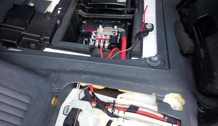
For convenience, I decided to power the new system as I had my original reversing camera and display: from a socket on the dash. This lets me unplug the kit from the vehicle battery and supply it from the leisure battery so I could calibrate and test the system without running the engine.
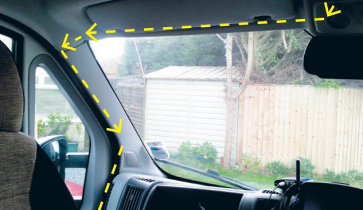
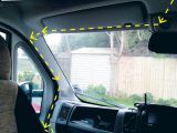
To keep the cables from the processor box hidden, I ran them behind the fascia (above the interior lights) and tucked them up in front of the sun visor. From there they were pushed down behind the plastic door pillar cover then under the inside lip of the rubber door seal.
I had a small plastic container inside the left-hand glovebox to act as junction box for power to and video from my original reversing camera. This became the end point cables because power and video connections were already present.
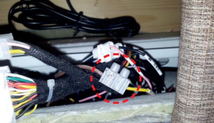
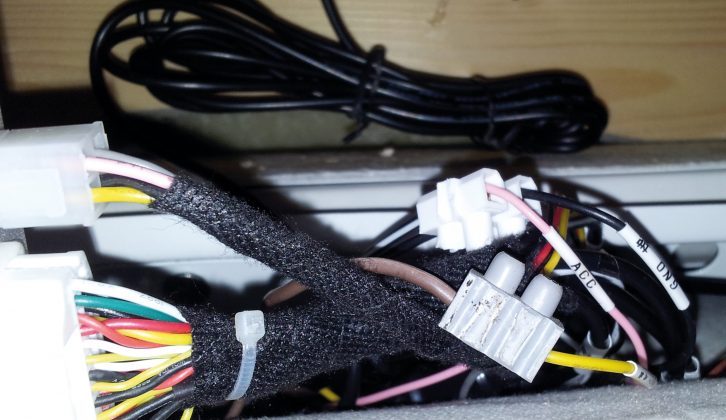
There are actually two power wires in the loom that supply the processor box. One is labelled VBAT+ and the other ACC. You can connect these wires and feed them from a switched 12v. The downside is that the system time will have to be set whenever the unit is powered up because there is no internal battery. It’s not essential but, if it isn’t done, the display will show a red warning box and the DVR recordings will not have the correct time stamp applied.
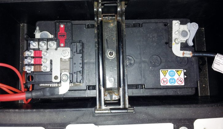
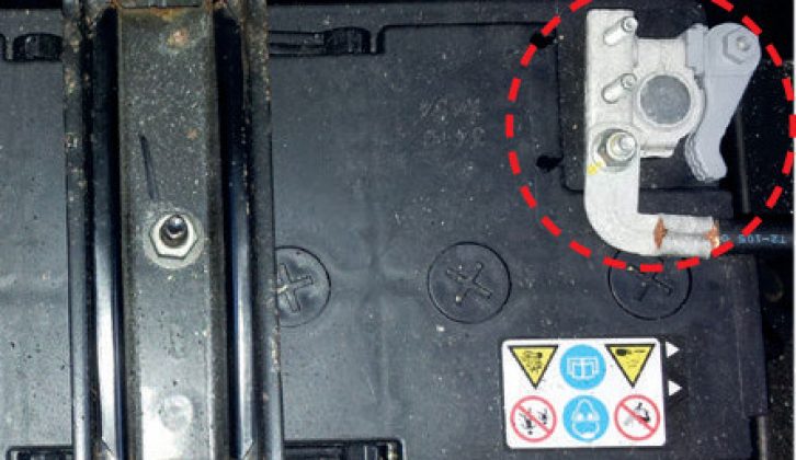
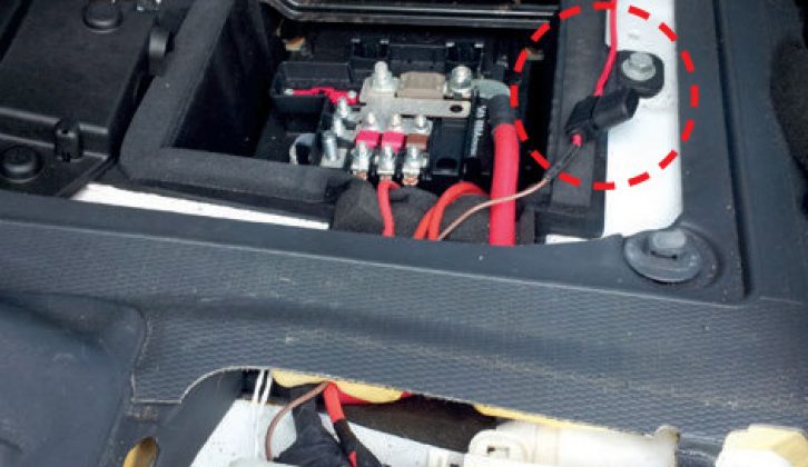
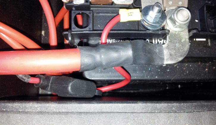
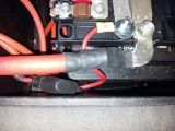
The alternative I chose is to run a ‘keep alive’ 12v supply to the processor box (VBAT+ wire) from the vehicle battery.
System set-up
I won’t go into detail about setting up the system, because the user guide is pretty comprehensive. Nevertheless, it is worth mentioning a few significant points about it.
Before I purchased the system I had asked the supplier several questions. One was whether the company could supply a PDF version of the guide.
They agreed to this and not long after they received my order, the PDF was sent via email. This proved extremely useful and enabled me to work out and understand various aspects of the system before it arrived.
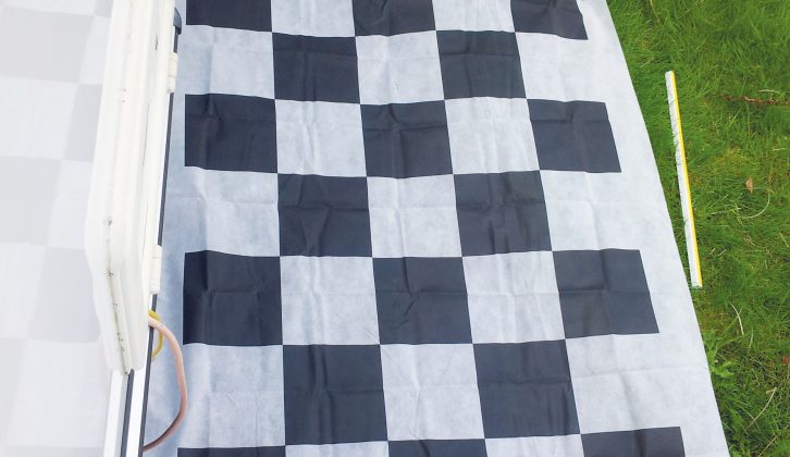
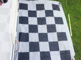
One thing that had mystified me was the ‘debugging cloth’. I’d initially thought that this was for cleaning dead flies off the cameras (particularly the front one). It turned out to be the main tool for calibrating the four cameras!
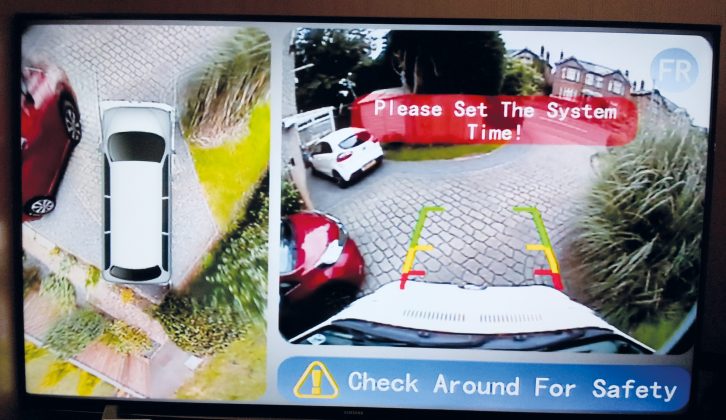
The importance of this material can’t be overstated because its chequered pattern is ‘recognised’ by the processor, via the cameras, when placed in specific locations around the vehicle. In conjunction with user-entered information regarding vehicle length and width, the system works out various operations, such as how the four camera images are to be ‘flattened out’ and merged to create the simulated overhead view.
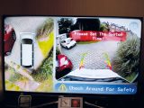
So what’s the system like to use? Amazing! Not only does the 360˚ view virtually eliminate low blind spots around the vehicle but it lets you review your journey via the built-in DVR function.
The system proved its worth during a recent visit to Wales when we met an ambulance and a minibus, in convoy, on a single-track lane. Reversing was our only option and the overhead view/rear camera display really came into its own.
The DVR function proved very interesting a while back after the Autoquest’s MOT test because the system records whenever the ignition is on. It occurred to me that it was likely that a good proportion of the MOT test had been recorded and, yes, it had! I had great fun watching the mechanic drive into the workshop, raise it on the vehicle lift and even call a couple of his colleagues over to look at the cab display!
Verdict
I have no doubt about the value of this type of camera system, particularly if reversing a vehicle of this size – with its blind spots – is not your favourite activity. This is a prime example of technology making a task easier and far safer.
One final point: I’d mentioned that I can swap the supply to my leisure battery. This allows some unanticipated and potentially helpful security applications; if the system is powered, it will, of course, record continuously.
It occurred to me that it was likely that a good proportion of the MOT test had been recorded and, yes, it had!
